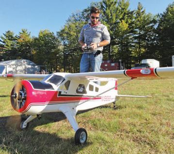
LET’S TALK GIANT SCALE — Radial Engine Upgrade
I lately constructed a DHC-2 Beaver from Hangar 9 (hangar-9.com). This airplane is designed across the Evolution 33cc two-stroke gasoline engine, however I needed so as to add the realism of a Saito three-cylinder radial engine (saito-engines.info). This four-stroke engine not solely affords an attractive engine sound but in addition provides the advantage of clear and extra economical gas consumption. Installing the Saito radial engine requires a brand new setup for the fuel-tank system, throttle linkage, and servo set up in addition to a number of different choices concerning the exhaust system. Let’s get all the way down to enterprise!
AIRFRAME MODIFICATION
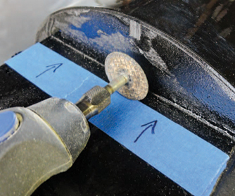
Using a Dremel outfitted with a cut-off wheel, the engine field is being trimmed to the right size required for the Saito 33 radial engine.
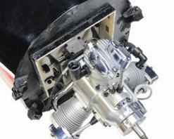
The Saito 33 radial engine has been quickly secured to the firewall. I used Zap ending resin to coat all uncovered wooden areas earlier than the ultimate set up of the engine.
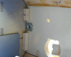
It is vital to strengthen important areas with spruce sq. or triangular inventory. As proven within the picture, instance parts embody the firewall and engine field.
Most giant-scale airplanes function an engine field constructed into the fuselage and secured at a number of factors for power. The Beaver isn’t any totally different. Its engine mounting field options higher, decrease, and facet frames, and also you then glue an already assembled engine field inside these frames. This engine field comprises the firewall and the bulkheads to safe the included gas tank. The size of the radial engine (with the included mount) is longer than that of the Evolution engine, so the place of the engine field must be adjusted. I measured the Saito 33R3’s size from 1/4 inch behind the propeller to the engine mount. I then put in the cowl utilizing that very same distance. I marked this dimension with a pencil on the within of the cowl. This confirmed the brand new location for the firewall. I then reduce away the surplus materials from the entrance of the engine-box construction in order that the engine (connected to the firewall) may slip into place. A Dremel Moto-Tool and a cut-off wheel did the job. A sanding block smooths the perimeters properly.
I made a firewall template (together with the engine mount bolt gap sample) and labored out the positions for the throttle arm, carburetor venturi, and the gas and vent traces. I then fabricated the brand new firewall, laminated collectively utilizing three layers of 1/8-inch plywood utilizing 30-minute Zap epoxy. For accuracy, I used a drill press for all required holes and openings. I bolted the engine to the firewall with 4 bolts and 8-32 blind nuts secured behind the firewall with medium Zap. At this level, I tack-glued the firewall into place and secured the cowl to make sure correct alignment. Once the engine was centered and the required propeller clearance existed, I traced the firewall’s location onto the within of the engine field. After eradicating the engine, I glued the firewall in place utilizing 30-minute Zap epoxy. I then glued 1/4-inch spruce inventory across the perimeter of the firewall (each the within and out of doors) for added power.
Because the brand new firewall is about farther contained in the field, I made a brand new fuel-tank tray to incorporate the throttle servo utilizing 1/8-inch mild ply and 1/4-inch sq. spruce. To hold the set up easy, the tray is similar width because the inside engine field. A bulkhead attaches the underside of the tray to the ground throughout the plane. I then bolstered all the things with the spruce inventory reduce to size, and I glued it into place.
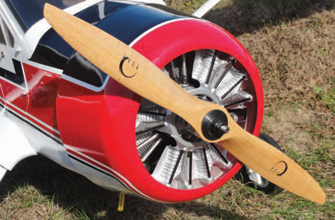
TIP OF THE MONTH
Keep Cool with Engine Baffles
Keeping your engine from overheating is necessary for constant efficiency. Building baffles throughout the cowl to make sure that cool air travels via the surfaces of the engine is advisable not solely on radial engines but in addition on all engines. My DHC-2 Beaver included a painted and completed dummy radial engine that matches into the entrance of the cowl. To present correct airflow, I marked the three places of the engine cylinders and made the openings barely bigger than the cylinders. After the dummy engine is put in, remember to open the underside of the cowl to supply twice as a lot air-exit space as the full of the three air-inlet openings.
I traced the perimeter of the tank onto a bit of paper after which made two 1/8-inch light-ply half-moon tank helps to safe the gas tank to the tray. I glued the tank to the perimeters of the helps with silicone adhesive to isolate the tank and soak up among the engine vibration. Once the helps have been secured in place, I reduce two slots within the ground in order that I may use a 1-inch-wide Velcro strap to safe the tank in place. I additionally retrofitted the included tank with tank-filter clunks from B&B Specialties (bbspecialties.com). These filters forestall overseas particles from coming into the engine. Because the Saito engine has an digital ignition module, I merely wrapped it in some Du-Bro (dubro.com) foam rubber and used Velcro to safe it below the tank ground. The ignition module has three spark-plug leads that match via a gap that I made within the mount field.
THROTTLE LINKAGE
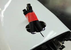
The preliminary exit for every of the three exhaust pipes has been reduce utilizing a Dremel, a cut-off wheel, and a sanding bit. Once the right location is confirmed, the opening can be enlarged to an ideal circle to permit for correct clearance between the airframe and the exhaust.
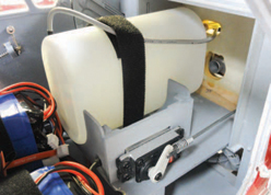
The gas tank has been put in and is held in place with a single Velcro strap.
I used a 12-inch-long, 4-40 pushrod for the throttle linkage and positioned the throttle servo on the tank tray. Making positive that the pushrod was perpendicular to the firewall, I marked the placement of the servo and used 1/8-inch mild ply to manufacture the servo mount. Once the mount was glued in place, the throttle servo and linkage was correctly put in. I sometimes use ball hyperlinks when the throttle-linkage geometry is offset. But as a result of I put in the throttle servo within the right location for a straight linkage set up, I used a normal threaded 4-40 clevis. I reduce the pushrod to size and used a Du-Bro 4-40 solder hyperlink on the servo arm. For a easy throttle response, it is very important use your radio’s endpoint adjustment to fine-tune the throttle-servo journey settings. Start on the servo heart place, and regulate every of the excessive and low throw settings in order that they’re about the identical. If the excessive and low journey values differ by a big quantity, the throttle response is not going to be linear.
MUFFLER INSTALLATION
The Saito 33 radial options three separate exhaust pipes, and the pipes are bent to form in order that they match via a gap on the underside of the fuselage. The ends of the pipes are tied collectively utilizing a bracket that clamps round all the pipes and is secured to the firewall.
As one other exhaust choice, Keleo Creations (keleo-creations.com) manufactures an exhaust collector ring for the Saito engine. Just as with full-size engines, the ring directs the exhaust out of the underside of the airplane. The collector ring has three particular person headers that safe to every cylinder. This exhaust system is inflexible and vastly simplifies the exhaust set up when the world throughout the cowl is restricted.
FINAL THOUGHTS
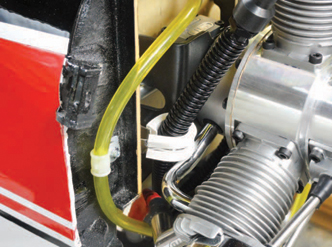
Vibration-damping clamps have been used to carry the exhaust pipe away from the engine mount and the throttle pushrod.
Using an engine that’s totally different than the one your airplane was designed for would require some modifications to the airframe. Using correct, well-thought-out development and setup methods will lead to an plane that may function correctly and final for years.

