Engine Swap Using Your Step-Ladder!
One method to mount your new or substitute engine in a mannequin is to make use of a ladder! Yes, that’s proper, an atypical step-ladder you possible have round your store!
To mount an engine on the very first level of including the engine, or including a brand new engine to an previous mannequin, you may have little or no method to assist your airplane when you attempt to calculate the ultimate place whereas horizontal on the workbench. You want to find out correct clearance for the prop and/or spinner in entrance of the cowl. I’ve discovered that one of the best ways to do that is to vertically mount your project-in-progress on a step-ladder!
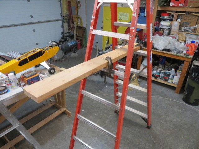
Figure 1. Not to maintain you questioning: a step-ladder, three clamps, and a 2×6 are the fundamentals. Find the appropriate peak on the steps on your undertaking.
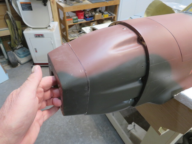
Figure 2. But first, we’ll talk about that you might have a airplane you picked up at a swap meet that wants a brand new engine and a number of TLC (Tender Loving Care). This P-40 wanted a brand new engine that was extra according to the facility it deserved, a DA-60. To match the brand new engine, this required the entrance finish of the fuselage/firewall to be pushed again about 3 inches. This required rigorously marking after which sawing off the unique mounting flange. It takes a little bit of braveness and also you want to have the ability to make some important measurements earlier than tackling this job! In this instance, I snagged a reasonably uncommon Troy Built 93-inch P-40E that was in want of rescue!
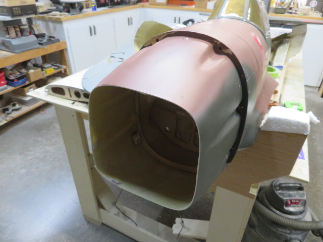
Figure 3. I’m dedicated now! Definitely left a gaping gap there!
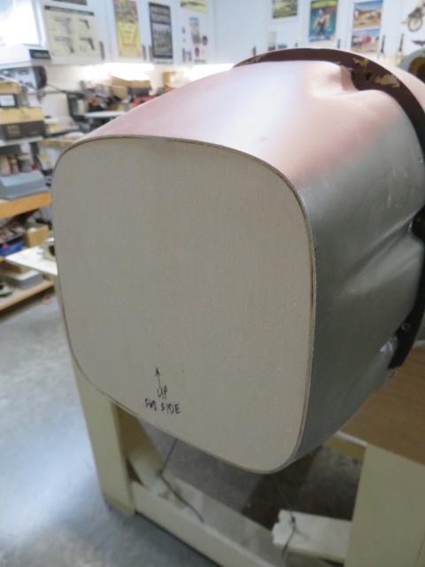
Figure 4. Beginning of the answer. A brand new internal, 1/4-inch firewall, is minimize to suit contained in the fuselage and the outer firewall will likely be epoxied in entrance. On a big RC warbird like this 93-inch P-40, it’s obligatory that you’ve a enough firewall and doubling the thickness on this case provides that additional safety.
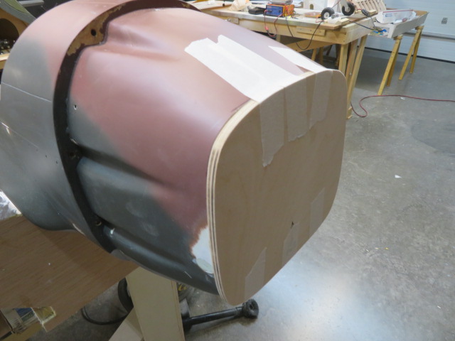
Figure 5. Once the internal firewall is epoxied into place, the outer firewall is epoxied in entrance. Use 30 minute epoxy, not 15 minute as you want good penetration into the plywood. Z-Poxy ending resin can be utilized as properly, however ensure to brush the resin on BOTH halves of the firewall, not only one half.
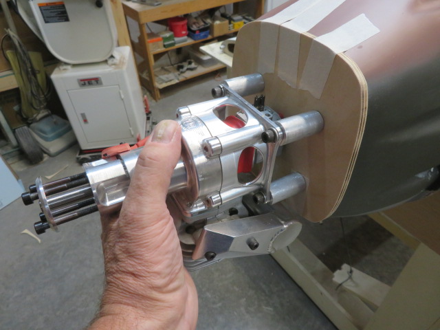
Figure 6. A sneak-peek earlier than going ahead. We are getting someplace now. But mounting this engine with the fuselage horizontal on the bench will likely be troublesome. This is the place it’s possible you’ll end up with a model new mannequin or a re-engining an older mannequin – mounting the engine sq. and true to the firewall, and on the similar time according to the cowl and spinner. This is the place it is advisable to go vertical!
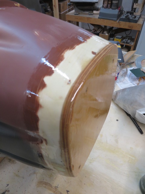
Figure 7. But first, the brand new firewall is glassed to the nostril with 2 inch glass tape and Z-Poxy resin. Take the time to present the brand new plywood 2 coats of Z-Poxy resin to fuel-proof and enhance look.
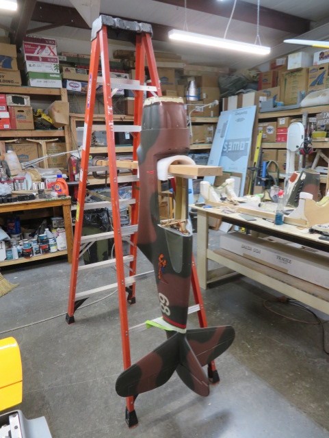
Figure 8. Now, with the brand new firewall accomplished, again to the step-ladder and punctiliously setting the P-40 as plumb and stage as potential on the two×6 with padding. Note the tape holding the tail-end plumb.
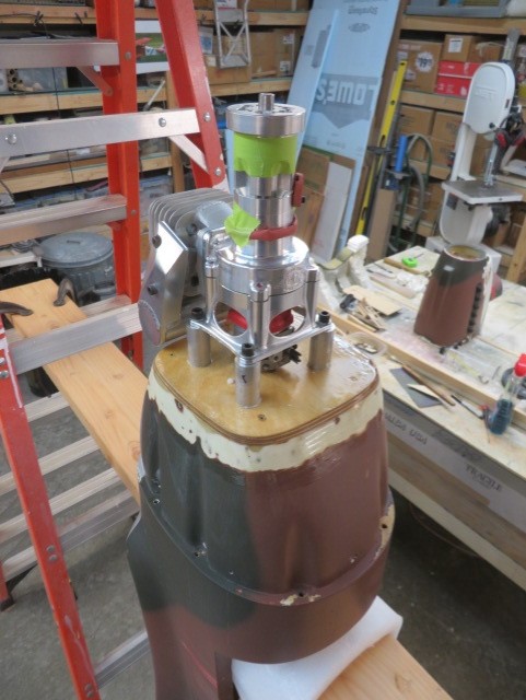
Figure 9. With the P-40 safe, the DA-60 is about on the firewall. Once you might be assured it isn’t going anyplace, set the cowl over the engine.
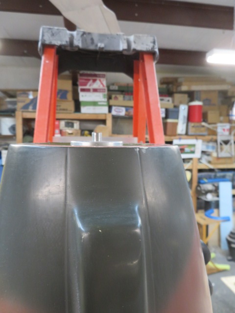
Figure 10. First factor to verify is to see if my calculations had been right on how a lot to chop off the nostril again in Figure 2. Seems about proper with the prop mounting again plate standing pleased with the cowl by 1/4 inch. And now you possibly can see how this kind of sensible testing wouldn’t be potential with the airplane horizontal on the work bench. This isn’t guesswork, it’s the actual deal, wanting bolting it to the firewall. Now, to not panic, in case your earlier calculations in Figure 2 usually are not fairly proper, you possibly can both shorten or lengthen your standoffs to set the report straight.
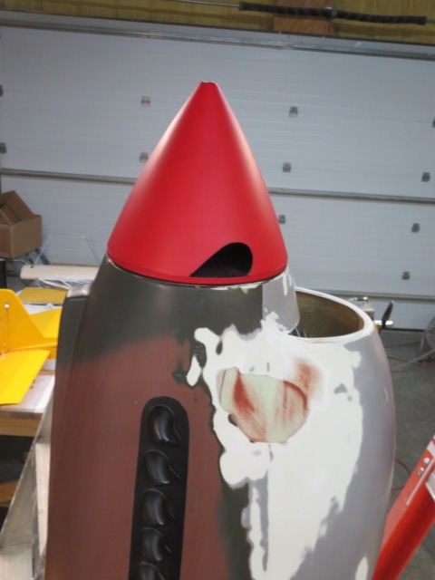
Figure 11. With the spinner and backplate on, seems to be like a great vertical alignment. This can also be the time to ensure the horizontal positioning for the spinner is correctly centered on the cowl.
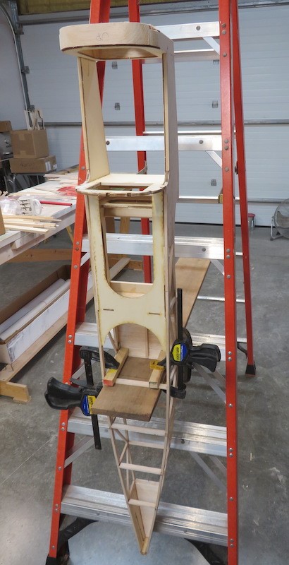
Figure 12. Let me interject right here with a photograph or two of establishing a model new mannequin with an engine. This is a 1/4-scale SE5a construct and the setup is mainly the identical as for the P-40. However, it’s important to be very cautious with the fuselage at this stage of the construct as it’s a bit fragile. Make positive all of your balsa joints are properly glued! If you’re taking your time and are cautious you can be OK.
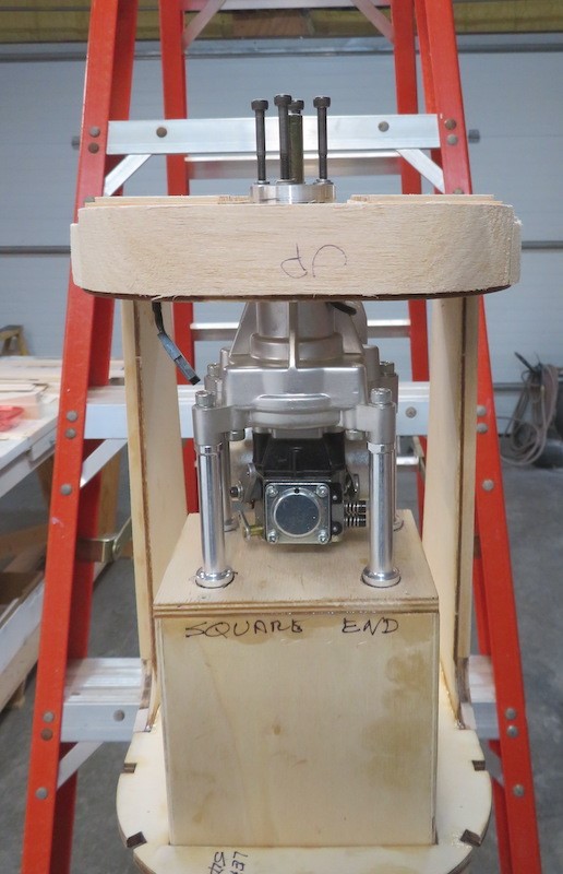
Figure 13. Here is the fuselage with the engine and standoffs in place sitting on the engine field. It is centered with the prop shaft 1/4 inch previous the entrance of the “radiator” shell louvers and centered within the opening. The engine is a DLE-35A. This time, I used a high-quality level pen to mark the standoff factors. Also, the sliding engine field ought to be marked to indicate how far ahead/aft it’s to finish the alignment. On the work bench, after you have the engine bolted to the firewall and the engine field tack-glued to the previous, you possibly can put it again on the step ladder to recheck the engine positioning earlier than the ultimate gluing.
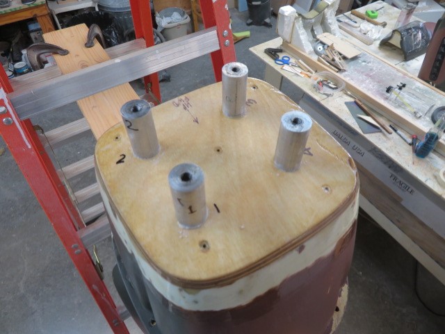
Figure 14. Back to the P-40. Carefully raise off the spinner, take away the cowl, (go away the engine on there in order to not disturb the alignment) and use CA to tack the standoffs the place they sit! Don’t fear, you might be utilizing thick CA and it received’t adhere completely. Then take away the engine leaving the standoffs tacked in place.
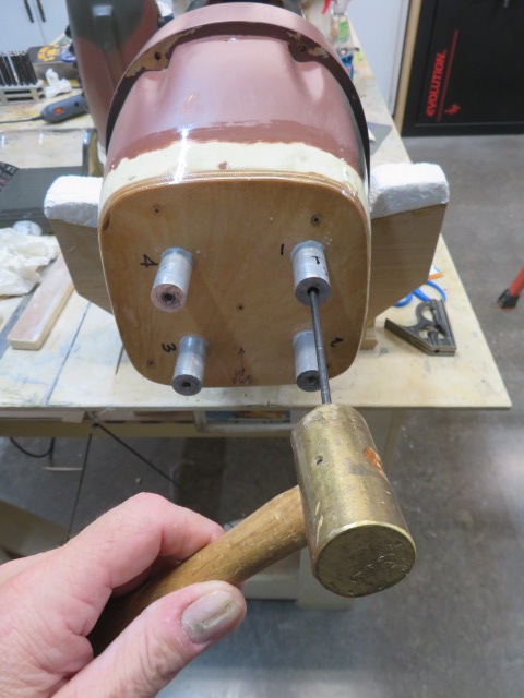
Figure 15. With the P-40 again on the bench, take a switch punch and mark all 4 standoffs factors with a lightweight faucet. You do that in case one of many standoffs pops off earlier than you possibly can drill a pilot gap.
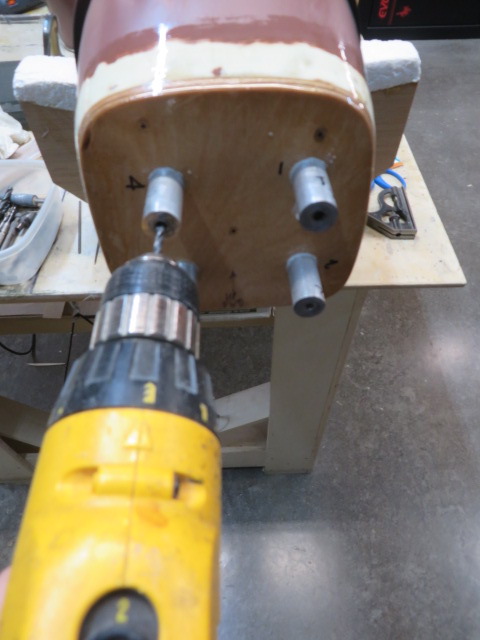
Figure 16. Go forward and drill a pilot gap if the standoffs are hole as on this case.
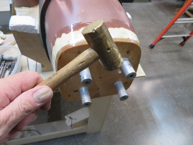
Figure 17. Simply faucet off the standoffs and drill for the T-nuts. Sand off the dried CA.
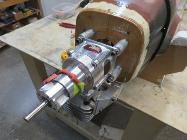
Figure 18. You can now add T-nuts on the bottom of the firewall and mount your engine with lengthy cap screws. I usually use 1/4-20 cap screws on a big, highly effective engine just like the DA-60cc.
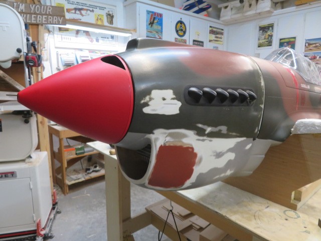
Figure 19. Now that you’ve the engine fully bolted on, you possibly can see the spinner and cowl becoming excellent, which might have been very troublesome and not using a vertical engine mock-up utilizing a typical step-ladder.
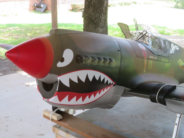
Figure 20. Can’t go away you hanging, that is the P-40 after the engine substitute and loads of TLC! Engine working full tilt! But notice that I’ve the P-40 properly lashed right down to the run-table at 5 factors and 60 kilos of weight on the bottom of the desk! Always take into account your private security as the very best precedence.
TEXT & PHOTOS BY LANE CRABTREE
