Building a Kit? Read these 10 tips first!
KIT BUILDING 101
Article and Photos by Gerry Yarrish
Our RC interest has been round for a lot of many years, and it has been, for essentially the most half, a hands-on DIY pursuit. In the start, all there was to select from have been builder’s kits. In current occasions, the interest has advanced to incorporate easier-to-assemble “almost ready to fly” (ARF) planes, which tremendously sped the event of skilled RC pilots. This, nonetheless, got here at the price of modelers having much less workshop expertise. This article highlights among the fundamentals of constructing a mannequin airplane from a equipment. Let’s get began.
Tech Tip
Rule primary for equipment constructing: Read the directions. Read them a number of occasions earlier than you start to attach issues collectively. If you might have problem understanding them, attain out to an skilled buddy for assist. You have to know what you’re doing and how you can do it earlier than you start.
STEP 1 CREATE A HEALTHY WORK ENVIRONMENT
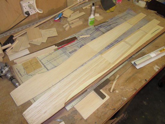
One of the very best elements of being a model-airplane builder is placing collectively a specialised workshop. Most of the time, this occurs in a nook of the storage or within the basement, so you may include all of the wooden shavings and never get the remainder of your private home soiled. All you really want is a bench or two, and these may be made out of cheap interior-grade hollow-core doorways and 2X4 lumber from a home-improvement middle. Your bench must be straight and true, and reality be advised, your workbench must be your first constructing undertaking if you wish to turn out to be a equipment builder.
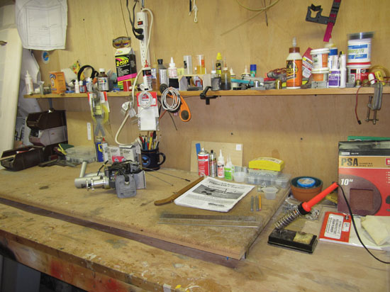
A neat workbench is a good begin for any constructing undertaking, whether or not it’s a equipment or an almost-ready-to-fly.
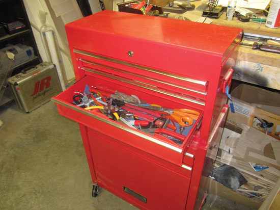
Keeping your bench clear, organized, and effectively lit will go a good distance in rushing the model-building course of. A helpful shelf above your bench is sweet for storing often-used provides and a roll-around toolbox/cupboard retains instruments helpful and inside simple attain. I’ve additionally discovered it helpful to make a smaller work board topped with stick-on cork materials to be used as a secondary work floor. You can assemble and construct lengthy elements on the primary workbench whereas assembling smaller gadgets, like tail surfaces and wing halves, on the constructing board. This is extra handy should you don’t have the room for 2 full-size benches in your work space.
Keeping your instruments helpful and inside simple attain with a roll-around instrument cupboard speeds building.
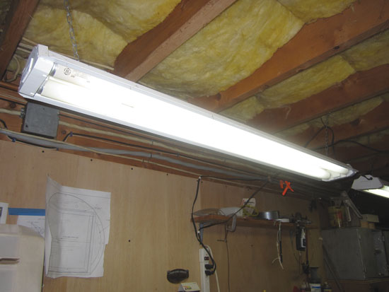
Good overhead lighting is a should. You will take pleasure in constructing extra should you can simply see what you might be doing. Ceiling store lights—particularly, single and twin fluorescent lighting—is surprisingly cheap and available at {hardware} shops and home-improvement facilities. Hang them over your workbench above head-banging peak. While you might be at it, set up a few store energy strips to be able to simply provide energy to the sunshine fixtures and your energy instruments.
Fluorescent or LED lights are a should. You will take pleasure in constructing extra should you can simply see what you might be doing.
STEP 2 GENERATE A PLAN OF ATTACK
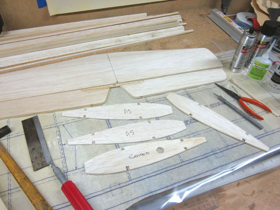
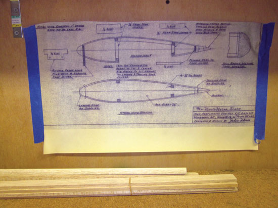
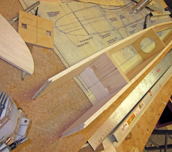
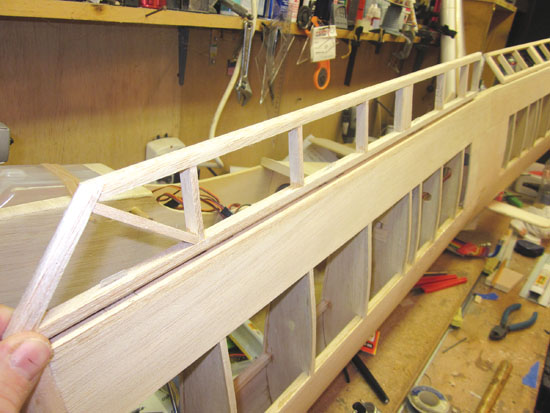
This is the primary distinction between kits and ARFs: You should construct the equipment aircraft, and that requires plans, that are normally included with the equipment elements. A great way to cope with the plans is to chop them aside and separate the varied elements into smaller sections. Some of the drawings (cross-sections and particulars) present how issues go collectively. I prefer to tape these to the wall in order that they don’t take up room on the workbench and I can consult with them all through the construct with out interruption. Place the drawings for the tail surfaces, fuselage, and wing panels in your work floor to be able to construct the elements on high of them. I like to start out constructing kits with the fuselage first since all the opposite elements are hooked up to it. If that is your first equipment aircraft, begin with the smaller tail surfaces and construct them on the separate constructing board.
Here, the 2 fuselage sides are being assembled. The positions of the elements are decided by
measuring them from the plans.
Use the side-view drawing to work out the position of the formers and doubles that the edges are made up of. When it involves gluing the 2 sides of the fuselage along with the formers, use a straight reference line as a information. Draw centerlines on all of the formers after which, as you add the formers and draw the edges collectively on the tail, align the centerlines with the reference line. You can draw a line on the workbench or use one of many border strains which are drawn on most plans.
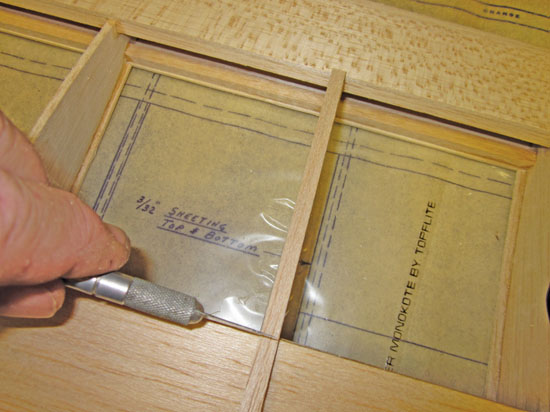
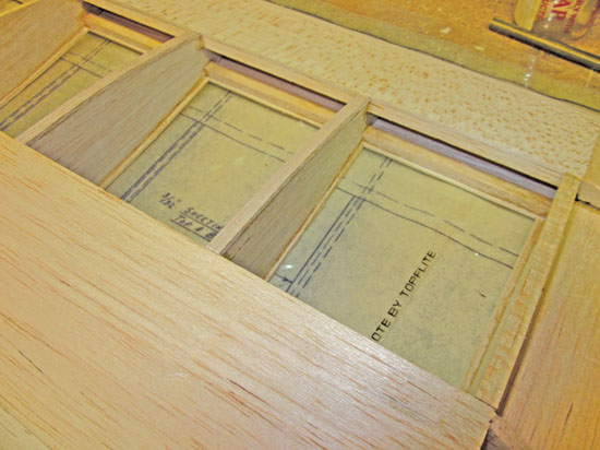
It can be vital to guard your plans to stop your elements from being caught to the paper. I take advantage of clear plastic Plan Protector from Great Planes, however you can too use clear movie overlaying. You may also use small sheets of wax paper or plastic meals wrap positioned beneath particular gluing factors to guard your planes.
Whether you employ industrial plan protectors or some plastic meals wrap, stopping your elements from sticking to the paper is vital.
With plan particulars taped to the wall, you may consult with them throughout building they usually received’t take up room in your constructing floor.
STEP 3 ENSURE PROPER ALIGNMENT
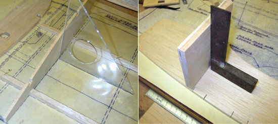
As you get into the construct, you will need to use squares and 90-degree triangles to assist preserve elements sq. and correctly aligned as your glue joints dry. Measure your facilities and draw centerlines on elements to be able to, at a look, see if they’ve been put in accurately. When you construct a wing panel, you first begin by pinning the underside spar securely in place over the plans. You then add the varied ribs to the spar, ensuring they’re positioned vertically utilizing a builder’s triangle as a information. Tack-glue every rib into place after which, after putting in the highest spar, end gluing the ribs into place. Always take your time and ensure all the pieces strains up correctly earlier than ending the gluing.
Use squares and 90-degree triangles to assist preserve elements sq. and correctly aligned as your glue joints dry. Measure your facilities and draw centerlines on elements to be able to, at a look, see if they’ve been put in accurately.
Tech Tip
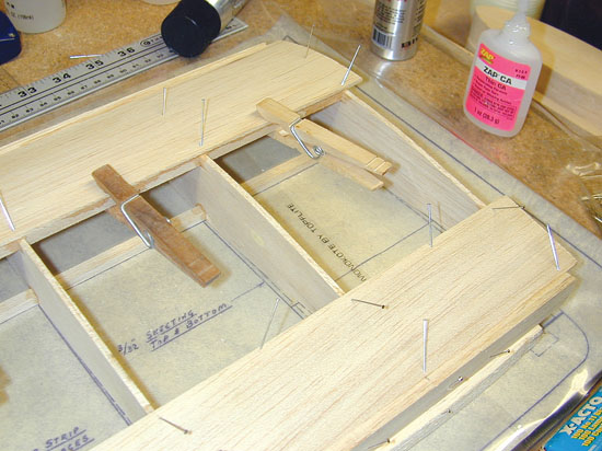
There are loads of glues to select from on the interest outlets. As a common rule, CA glue is available in skinny, medium, and thick viscosities. Use skinny CA for tight-fitting joints and medium CA for the place there is likely to be a slight hole between elements. Thick CA glue normally takes a bit longer to dry, so it’s a good selection when gluing elements collectively the place you’ll want a bit extra time to get the alignment right, reminiscent of for lengthy items of wing sheeting. Straight pins, tape, and clothespins are all nice for holding items collectively because the glue dries.
STEP 4 MAKE CLEAN CUTS
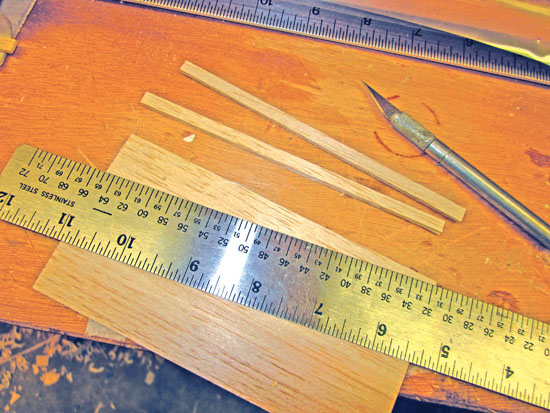
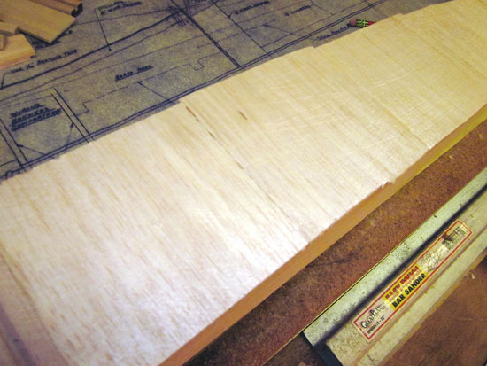
When it involves chopping elements to form or to suit, at all times use a pointy hobby-knife blade. As you employ them, the blades will turn out to be uninteresting, and it will have an effect on the standard of the reduce. Using uninteresting blades additionally requires extra chopping strain, and this may be harmful since you would possibly slip when making the reduce. Make your cuts, utilizing a straightedge as information, then make a number of mild passes to finish the cuts in balsa sheeting. For gadgets like main edges, spars, and different “stick” inventory, I discover it useful to chop them longer than wanted. I glue them into place, then use a razor noticed to chop off a lot of the extra size; I end it off utilizing a sanding block. This produces a clear and correct completed meeting. This is particularly vital for the wing middle ribs, the place the wing panels are glued collectively, and for the wingtip ribs, the place you’ll later connect the wingtips.
STEP 5 BUILD TO SUIT
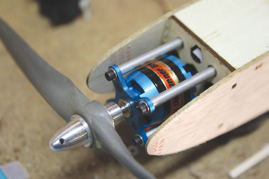
An vital a part of constructing a equipment is the strategy planning stage. You should determine early on what radio gear and servos you will use, and what sort of energy system you intend to put in. Having your {hardware} helpful makes your construct go smoother as you may prep numerous elements earlier than they’re glued into place. Take the firewall, as an example. With my newest construct, I went with a Himax brushless motor from Maxx Products for energy. Before gluing the firewall into place, I used the motor-mount {hardware} to find out the place the attachment holes wanted to be drilled. The similar goes for the servo rails. By having the servos readily available, you may decide the servo-rail spacing. Having the battery pack and velocity controller, you can too work out the place all the pieces might want to match earlier than gluing formers and doublers into place.
Part of this planning additionally contains the format and set up of your pushrods for the elevator and rudder. You have to work this out earlier than you end sheeting the highest and backside of the fuselage. It is extraordinarily tough to put in pushrods and their information tubes after all of the sheeting is in place. Also, bear in mind to put in the highest and backside sheeting in order that the grain runs throughout the width of the fuselage. This provides extra energy than should you ran the grain from nostril to tail.
Glue the highest and backside fuselage sheeting (cross-grain) in place after putting in the pushrods and information tubes.
Here is the Himax motor powering my new undertaking. I used the motor mount to find out the position of the attachment holes.
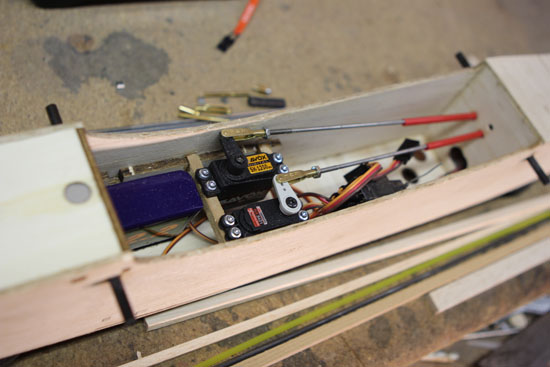
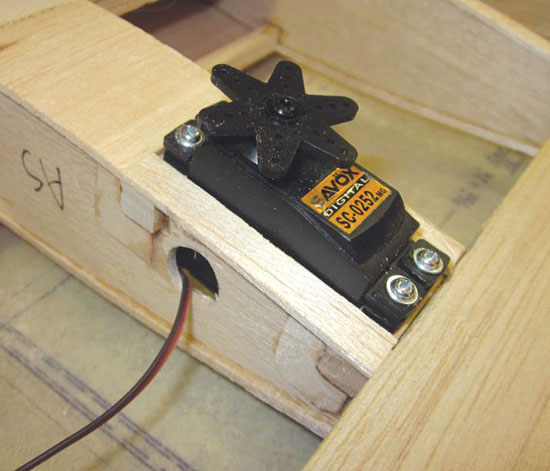
When putting in your servos, ensure that the servo arms don’t intrude with the edges of the fuselage or another tools within the radio compartment.
STEP 6 SET UP YOUR LINKAGES
Since the pushrods switch the servo’s motion to the management surfaces, it is best to set up the servos first after which the management surfaces earlier than you may arrange the linkages. Be certain to make use of hardwood, reminiscent of spruce, and even 1/2-inch-wide strips of 1/4-inch-thick plywood to make sturdy servo mounts and rails. Install the rubber grommets and brass inserts into the servo’s attachment tabs after which drill pilot holes by them and into the servo rails. I take advantage of cap-head screws from RTL Fasteners for all my {hardware}, however most servos include servo mounting screws. Be certain so as to add a drop of skinny CA to the screw holes to assist “harden” the wooden in order that the screw threads received’t strip out.
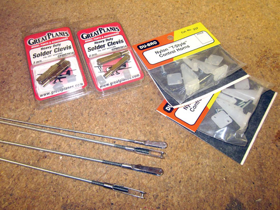
I like utilizing a mix of Great Planes and Du-Bro Products to make up my management programs. Twelve-inch-long pushrods with threaded ends and mating clevises can be found from Great Planes. It additionally has clevises which are soldered to the opposite finish of the wire pushrod. This setup works effectively and permits for about half an inch of size adjustment. For my giant 60-size Florio Flyer, I used this setup, with servos mounted simply in entrance of the stabilizer. Make certain you put in the Du-Bro management horns in order that the attachment holes line up with the hinge strains of the management surfaces.
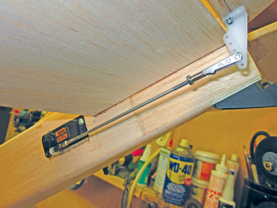
When you put in your management linkage, middle your management floor and fix your management horn in order that the holes are lined up with the hinge line.
STEP 7 SOLDER THE HEAVY PARTS
When it involves soldering large-gauge wire, reminiscent of for pushrods and clevises, at all times clear the elements with sandpaper and use high-silver-content solder and correct flux. Do the identical for soldering the wire touchdown collectively. I discover that Stay Brite silver solder and liquid flux work nice. It is vital to make use of loads of warmth when soldering; I take advantage of an 80-watt soldering iron with wonderful outcomes.
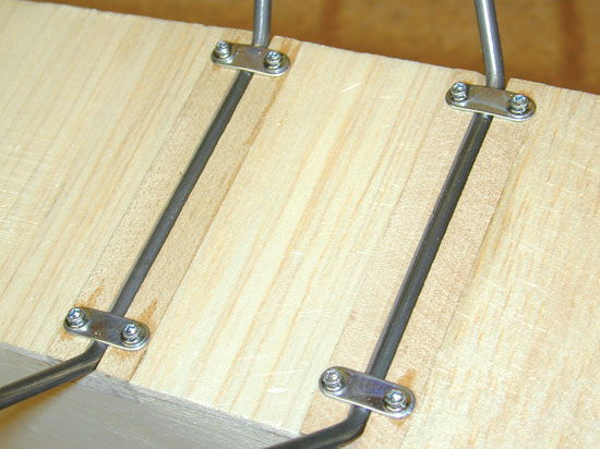
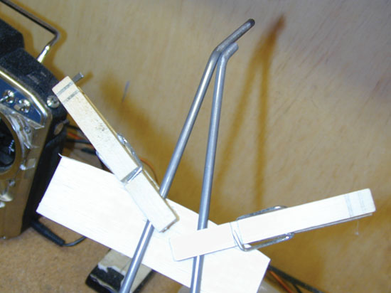
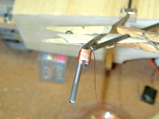
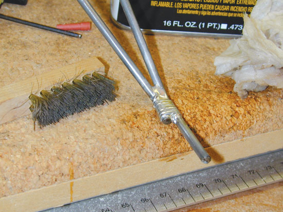
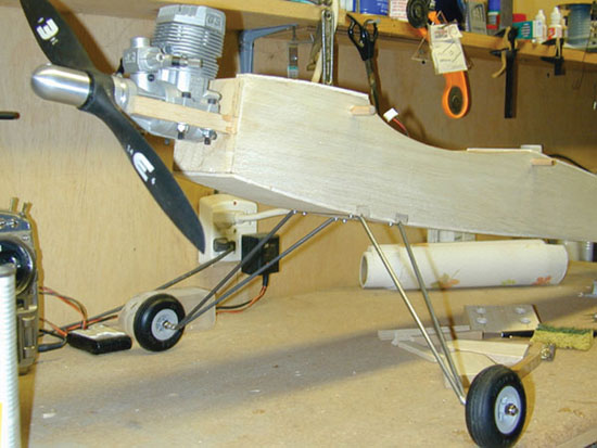
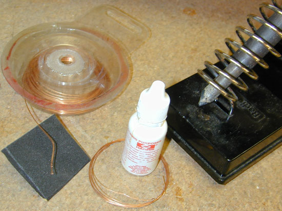 To find yourself with a straight and correctly aligned touchdown gear, you first have to wash all of the elements after which connect the bottom ends to the fuselage with the required straps. Next, use a size of wooden and a few clothespins to clamp the struts into alignment in order that the axles ends may be soldered collectively. I take advantage of skinny copper wire to bind the entrance and rear wires collectively, wrapping the solder joint space tightly and neatly. Apply a couple of drops of flux to the wire and the gear struts after which apply warmth. Place the soldering iron beneath the wraps, and apply the solder to the highest. When the wires and equipment struts are scorching sufficient, the solder will move easily into the joint space. Don’t transfer the gear till the solder has cooled. Check the alignment of the second aspect, and repeat the method to finish the job. After the solder has cooled, take away the gear from the fuselage and clear the solder joints utilizing a wire brush and a few solvent, reminiscent of rubbing alcohol, to take away the leftover flux. Install the wheel and reattach the touchdown gear after you’ve coated the fuselage.
STEP 8 JOIN THE PANELS
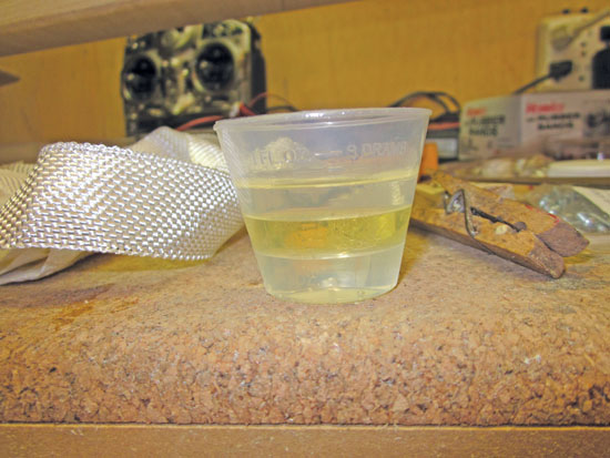
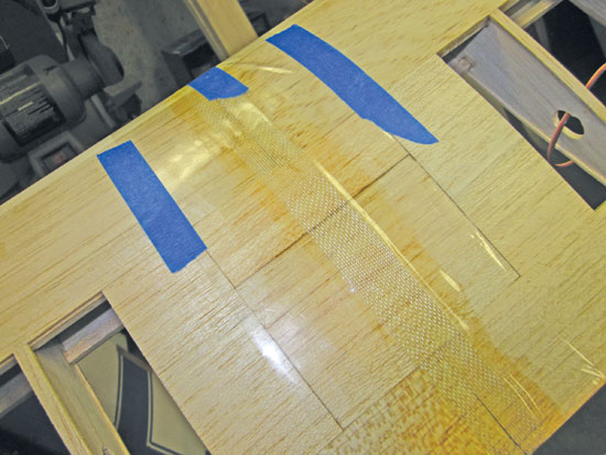
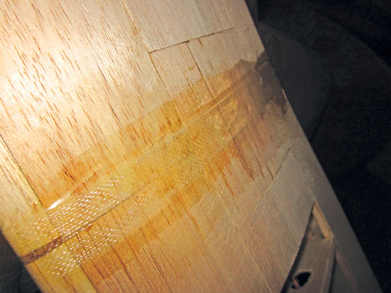
To strengthen the middle part the place the 2 wing panels are glued collectively, it’s important to wrap the middle seam with some fiberglass tape and glue it into place with slow-setting epoxy resin. To make the job a bit simpler, set up the fiberglass tape to the highest and backside surfaces individually and overlap the items on the main and trailing edges. To make the epoxy resin simpler to use, I take advantage of equal elements of half A and B after which some denatured alcohol in order that it’s all combined collectively in thirds. Lay the tape into place, dribble the resin on high of the fiberglass, then place among the clear plastic plan protector over the joint. Using some scraps of balsa sheets, squeegee the resin beneath the clear plastic in order that it utterly fills the weave of the reinforcement tape. Tape the clear plastic in place till the resin units up utterly. Then take away the plastic sheet, and repeat on the opposite aspect of the wing. When the job is finished, you should have a really clean floor produced from the plastic sheet and the overlapped sections of tape might be correctly bonded collectively and flattened out. No sanding is required, and the overlaying materials will stick properly to the graceful epoxy floor.
Here, the fiberglass tape and epoxy have been coated with the clear plastic. Left: After eradicating the plas
STEP 9 FIT THE HINGES
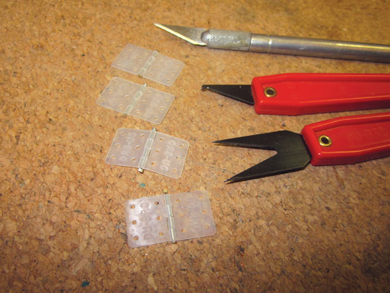
Once all of your elements are constructed and assembled, it’s important to match all of the hinges (however don’t glue them into place till after the mannequin has been coated). Du-Bro Products makes nice plastic pinned hinges, and you may get CA glue–type hinges from Radio South. It’s as much as you which of them one to make use of.
Properly put in plastic pinned hinges will present clean, bind-free management response. Du-Bro has a hinge-slotting instrument set that makes the set up simple.
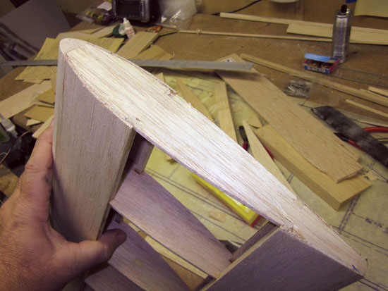
For lengthy management surfaces, just like the ailerons, you will need to set up all of the hinges in order that they’re in alignment with one another.
STEP 10 COVER AND FINISH IT
Ready for takeoff? Almost! Before you may fly your new kit-built mannequin airplane, you’ll have to cowl it. There are a number of manufacturers of coverings obtainable together with plastic movies, reminiscent of Hangar 9’s UltraCote and Top Flite’s MonoKote, in addition to painted material material, reminiscent of Solartex from Balsa USA and SIG Mfg.’s Koverall. Each model comes with detailed directions, however should you need assistance, ask an skilled buddy for help. It’s the overlaying and ending that really units your kit-built mannequin other than the remaining.
For a clean overlaying job, it’s important to sand all of your airplane’s elements clean. There must be no gaps or uneven glue joints. Using a sanding block is the very best methodology to provide a fair floor.

