Organize your firewall: Correct engine installation practices.

When you construct a giant-scale airplane, many selections will have an effect on the plane in a single kind or one other. With respect to the engine, just a few gadgets you must take into account embrace—however should not restricted to—the dimensions, weight, ignition, and gasoline sort. I’ll contact on just a few fundamentals of engine choice in addition to engine set up and associated parts. Whether you’re constructing from a equipment, assembling an almost-ready-to-fly (ARF) aircraft, or modifying a second-hand plane, it helps to grasp just a few vital areas to make sure that your plane is structurally sound and can stand the check of time.
The Right Engine
Many pilots new to large scale ask me whether or not they need to use a big glow engine or a gasser with a magneto or digital ignition. That relies upon. I proceed to make use of all kinds of engines for numerous causes. For a small large, just like the Hangar 9 Ultra Stick 30cc ARF, I would favor a bigger glow two-stroke to avoid wasting on engine weight and the extra weight that an digital ignition, swap, and battery add to the airframe. Fuel prices are a consideration, nevertheless, with bigger glow-powered engines as they’re typically thirsty.
Another choice is a gasoline engine with a magneto-driven capacitor-discharge ignition (CDI) system. I personal a Sopwith Camel that has a Zenoah G-38 with a magneto-driven CDI system and a handbook kill swap for security. Often, you’ll want an aftermarket spring starter or an electrical starter—just like the Dynatron from Sullivan, which may function
on 12 or 24 volts—to start out the engine on the discipline. These kinds of engines are easy as they don’t require a separate ignition module, battery, and swap. They are sometimes heavier in comparison with their electronic-ignition counterparts, however weight is typically wanted to attain the right middle of gravity.
Another sort of gasoline engine options an digital ignition. I energy my 1/3-scale Pitts Special with a Desert Aircraft 50cc engine primarily based on displacement, energy curve, weight, and ease in hand beginning with out an electrical or spring starter. This engine options an digital ignition, so just a few gadgets are required, similar to a battery, swap, and (beneficial) an optical kill swap.
Engine-Installation Fundamentals
Always start by trying on the engine and tools beneficial by the manufacturer. For the 1/3-scale Pitts, I in contrast the three-views offered by the engine producer to the firewall and cowl dimensions to substantiate that the engine would match with solely a portion of the cylinder and exhaust uncovered.
Measuring the gap from the firewall to the entrance of the cowl, I added roughly 1/8 inch to permit a enough hole between the cowl and the spinner backplate, and realized that I would wish to make use of standoffs. Typically, engines are mounted on to the firewall or to standoffs. Exceeding beneficial standoff lengths steered from the engine producer might lead to injury to the engine resulting from vibration. Desert Aircraft recommends utilizing standoffs now not than 3 inches for the DA-50R. Because I wanted extra distance, I laminated a number of layers of oversize 1/8-inch aircraft-grade plywood till I achieved the required distance. I all the time use aircraft-grade plywood as a result of it accommodates extra plies when in comparison with gentle ply, and having extra plies leads to higher energy and stability. If you utilize gentle ply, you could discover that the wooden compresses whenever you tighten the engine bolts.
Some plane producers provide templates for all kinds of common engines. At a minimal, most ARF fashions have horizontal and vertical reference traces on the firewall you can measure from, and you should utilize the plans when you’re constructing from a equipment. While drilling right into a 1/4-inch firewall is simple with a cordless
drill, I like to recommend utilizing a drill press whenever it’s important to drill into a number of layers of plywood.
I favor to make use of 1/4×20 SAE mounting bolts and washers to safe the engine in place. Because the standoff is threaded, you have to bolt the engine in place from behind the firewall. Simply insert the bolts and washers from the rear aspect of the firewall, by way of the plywood spacers, and into the rear face of every standoff. If you aren’t utilizing standoffs, use a washer and a locknut to safe every mounting bolt in place. Unless you utilize locknuts, thread-lock needs to be used on all engine mounting bolts.
Two unrelated gadgets are essential to notice earlier than continuing ahead. First, you want enough house close to the inlet of the carburetor for unobstructed airflow. If the carburetor is in entrance of the firewall, which it’s on this case, you want at the least 1 inch of clearance from the carburetor inlet. Second, when you discover that you have to change the thrust angle of the engine after the flight checks, you should be cautious to make sure that the standoff and every engine mounting tab are in the identical aircraft. Simply including a shim behind two of the 4 mounting tabs can break an engine mounting tab over time.
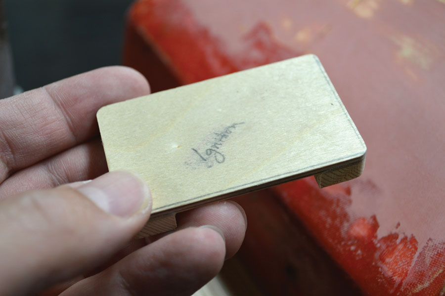
Ignition parts and wiring needs to be separated, to the utmost extent potential, from the receiver, receiver battery, servos, and so forth. A mounting location was chosen primarily based on the size of the spark-plug lead and surrounding gadgets (i.e., the engine mount, cowl, and many others.). To set up the ignition module, I made a plate that was the identical dimension because the perimeter of the module out of 1/8-inch aircraft-grade plywood. I then glued two 1/4-inch-square spruce rails at every finish of the plate to permit enough spacing between the firewall and the plate. As far as gluing the mount to the firewall, the mounting floor was ready, cleaned with rubbing alcohol and a paper towel, and epoxied in place utilizing 15-minute epoxy from Zap. The ignition can’t be rigidly put in to the airframe. To soft-mount the ignition module, I used 1/4-inch foam rubber from Du-Bro. I secured the froth rubber with hook-and-loop materials and likewise held the module in place with hook-and-loop materials with the addition of a hook-and-loop strap across the total meeting.
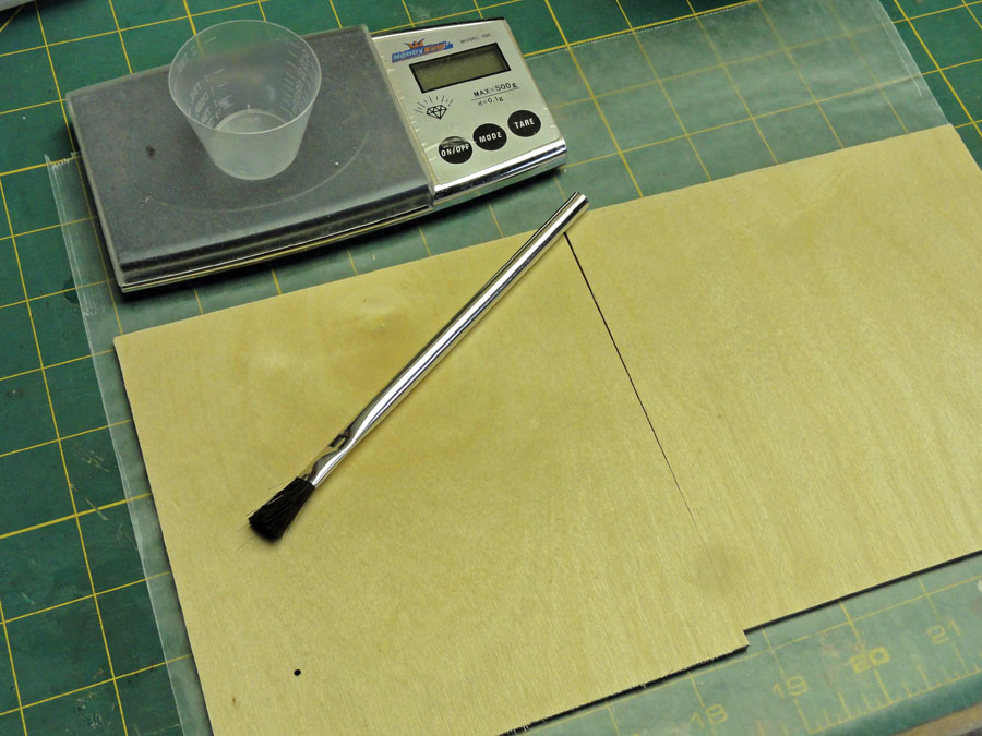
A scale is helpful to make sure that the correct quantity of resin and hardener is used when mixing epoxy.
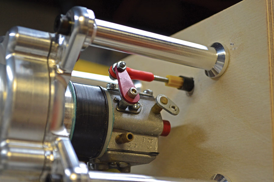
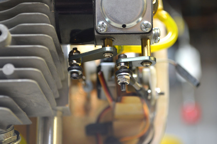
The throttle servo has been linked to the carburetor with a 4-40 ball hyperlink and 4-40 versatile pushrod.
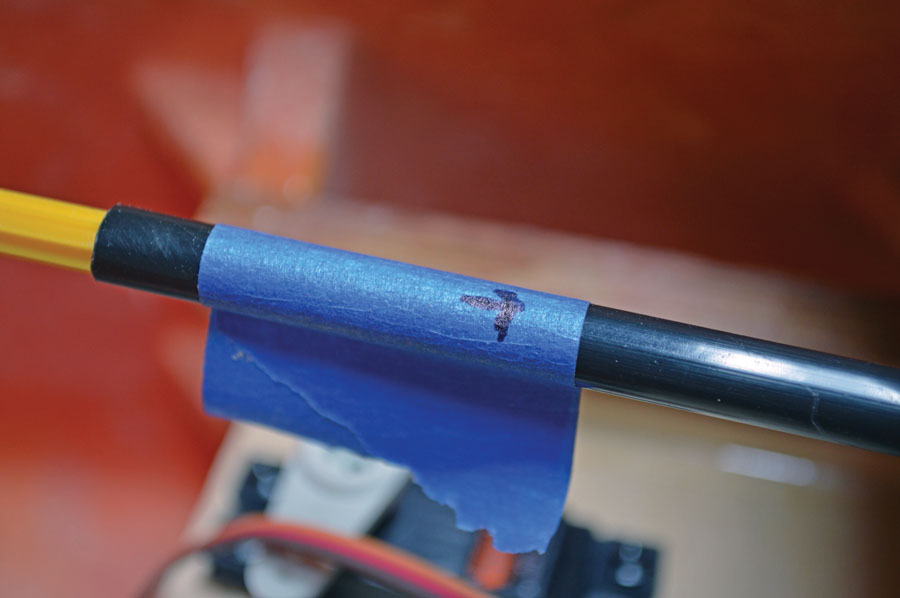
For the throttle servo, I made a decision to make use of a 4-40 versatile pushrod from Sullivan Products. The blue tape reveals the place the sheath should be lower to permit correct transferment of the interior nylon pushrod, threaded stud, and ball hyperlink.
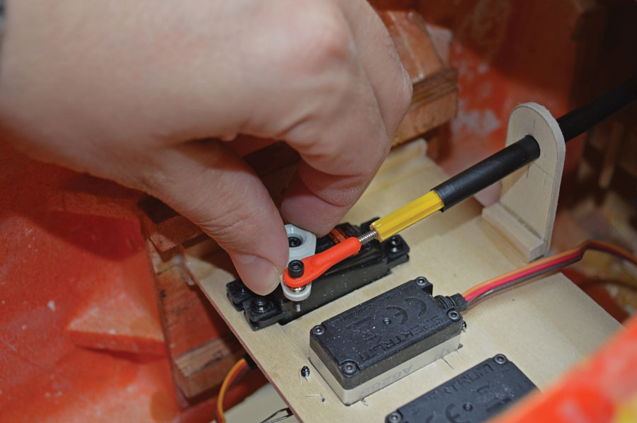
Because the throttle pushrod is sort of versatile and lengthy, it wanted a plywood pushrod assist to safe the black sheath to the plywood servo plate.
Geometry Matters
The geometry between the servo and the throttle arm on the carburetor is extraordinarily essential. To start, I measured the gap from the middle of the throttle shaft on the carburetor and the middle of the attachment level on the arm that’s secured to this shaft. This distance is what you need to have from the middle of the throttle-servo arm to the middle of the pivot level on the arm itself. Far too typically, I see people use a 1.25-inch servo arm on the throttle the place the gap is far smaller on the automobileburetor. This leads to low adjustable journey quantity numbers, extraordinarily poor decision, and infrequently a nonlinear really feel whenever you transfer the throttle stick on the radio and watch the response from the servo.
On the Pitts, I mounted my throttle servo on the identical servo tray that I used for the rudder and elevator servos. I did this in order that I might simply entry the servo because it was immediately below the cockpit ground. With the throttle-servo arm and throttle arm on the carburetor at completely different heights, I opted to make use of a 4-40 versatile pushrod from Sullivan Products. The versatile pushrod incorporates a 4-40 black/gold threaded stud that screws into the interior rod, and sometimes, a clevis that’s hooked up to the opposite finish of the stud. I used a 4-40 ball hyperlink at each the servo and carburetor areas, and added an 1/8-inch plywood assist to brace the pushrod in order that it wouldn’t flex by way of the complete vary of movement from the servo. I used Zap Goo to safe the sheath to the plywood assist as this adhesive is ideal to make use of for bonding wooden to plastic.
To discover the correct drilling location on the plywood spacers and firewall for the pushrod tubing, I noticed the complete vary of journey from the carburetor throttle arm and marked every endpoint in addition to the middle by aligning a pushrod, with paint on the tip, with the carburetor attachment level whereas the pushrod was parallel to the engine standoffs. I then moved the pushrod in order that the paint would contact the plywood spacers. With the spacer plate being marked, I might now drill by way of the spacers and into the firewall to insert the pushrod meeting.
Like the throttle linkage, a choke linkage is obligatory for gassers which have a Walbro carburetor, just like the DA-50R. You do have choices, nevertheless. On the choke, for instance, you should utilize servo management or a mechanical linkage that may be operated by hand. Regardless of the strategy, it is vital that the choke is allowed to completely open and shut. If it doesn’t shut, it is going to be tough to prime the engine. On the opposite hand, if it doesn’t absolutely open, the engine will run however will probably be unable to run at most energy.
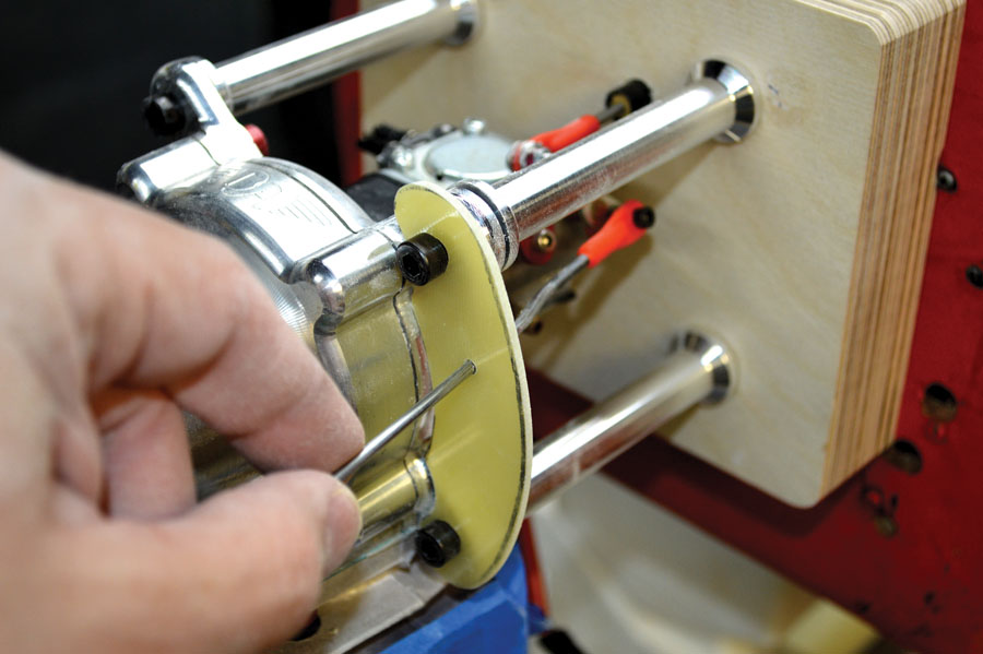
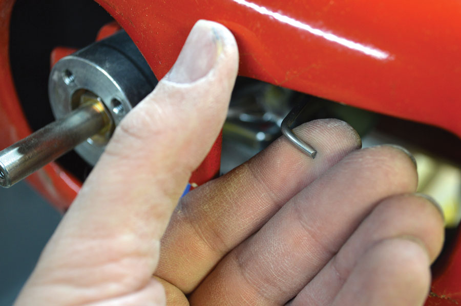
For the Pitts, I made a assist out of G-10 Garolite, a fiberglass-laminate composite materials. Because it’s tough to chop and requires using a rotary software and belt sander, you will need to use a correct respirator to keep away from inhaling glass and epoxy mud. In reality, it’s an excellent follow to all the time use a respirator for sure adhesives, composite supplies, and so forth. The G-10 assist plate has two holes for the engine mounting bolt to go by way of in addition to a 3rd for the choke linkage, the place I might entry the pushrod by way of the left engine-inlet opening on the cowl.
With the engine mounted, the throttle servo and linkage linked, and the handbook choke pushrod secured, it was time to put in the ignition swap and battery. The battery plugs into the swap, and the swap is then plugged immediately into the ignition module. I opted to safe a Spektrum three-wire swap harness to the fiberglass cowl. The wire size was lengthy sufficient that the ignition battery might be put in throughout the fuselage and simply accessible for charging functions. I favor to disconnect my ignition and flight batteries after a given flying session for security. If you favor to make use of a higher-voltage battery supply, use a voltage regulator and easily join the swap to the voltage regulator, which is then plugged into the ignition module. On this explicit engine, the facility supply for the module should be between 4.8 and 6 volts. I made a decision to make use of a Spektrum 6.6V 1450mAh LiFe battery. While the manufacturing unit recommends a 180mAh or bigger capability pack, which needs to be enough for 5 or extra flights, I estimate that on a given outing I’d not be flying this plane as a lot and determined to make use of a barely smaller battery.
The ignition plate was constructed utilizing 1/8-inch aircraft-grade plywood and two 1/4-inch-square spruce rails.
I made the G-10 choke-linkage assist in such a approach that it tied into two of the 4 engine mounting bolts.
As you possibly can see, the choke linkage is definitely accessible by way of the cowl of the 1/3-scale Pitts Special.
While we mentioned utilizing a handbook choke linkage, you can even use a servo to function the choke.
Final Thoughts
We’ve mentioned just a few completely different engine choices, their functions, and some enjoyabledamental construct practices to implement in correct set up methods. This column is supposed to function a information and enhance your understanding of basic setup practices. Seek the recommendation of a fellow skilled builder, and luxuriate in this wonderful sport.

